Click on circuit above for full size view or download
Mother invented necessity so I just had to do something about it. This project is for a pulse width modulated dual drill speed controller. For driving small, low voltage, DC drills and using switch mode topology. This is not the easiest stuff in the world to make happen and is not recommended for the beginner. It is relatively safe to work with but not trivial and could still be lethal if built by an idiot. As always I take no responsibility for any misadventures with this information. It is published purely out of interest. However if you do get into this stuff then you're welcome to drop me a line about it.
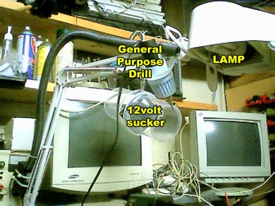
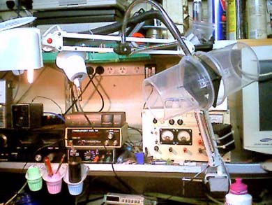
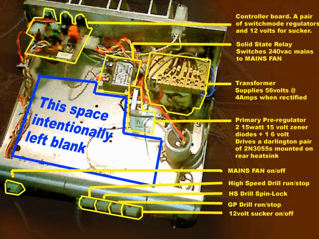
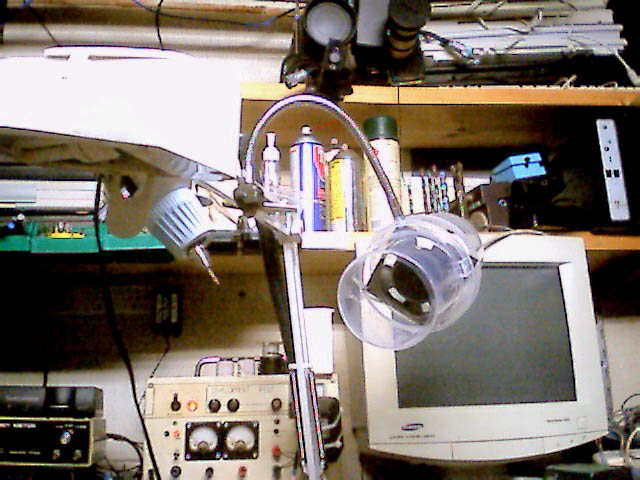
The necessity was that I had 2 DC drills. Both of which were in need of something better than what was driving them. Especially after a recent bench upgrade and reorganization. It's a long story but a simple variable linear regulator wasn't going to cut it. The problem being that the lower the speed, the less torque the drills have. PWM (Pulse width modulation) is ideal for this kind of work in theory but it's not without it's problems either. One is complexity. On the surface, the finished project looks pretty simple but it was not trivial to develop. The chips used are UC3843s. These are fairly common SMPS (Switch Mode Power Supply) controller chips which I acquired from a dealer on eBay. They turned out to be not very helpful for my original intentions and operated somewhat differently to what I had anticipated. They are used here, in a somewhat unusual configuration for a number of reasons. Mainly this is because I didn't have any power MOSFETs on hand and could only draw on a range of fairly ordinary power, bipolar transistors. This presents two immediate problems. The chips were designed to drive the high impedance gate of a MOSFET. Usually a 10 ohm resistor is all that separates the output and the gate. The chips run too hot and can fry when driving the base of a transistor like this so the resistance had to be increased and a diode placed in the path to protect the output from excessive current when it tries to drive the base low. The second problem is that a MOSFET is generally used because of it's extremely low Ron. On Resistance. That is to say, when the MOSFET is switched fully on, the resistance between drain and source is very low. These days, a fraction of an ohm is not uncommon. The lower the equivalent on resistance means the less energy that is wasted in heat through the transistor. They still get hot but considering the amount of current they pass they tend to run comparatively cool. By contrast, any given bipolar transistor will exhibit around 0.7 volts drop between collector and emitter. This translates into a huge equivalent on resistance depending on the voltage and current being switched. They tend to heat up rather quickly. This presents one of the two huge advantages of a switch mode power supply as compared to a linear. The MOSFET is either on or off. When on it has an extremely low resistance. When off it has as close to an open circuit as you can get. By contrast, a linear regulator such as the two pre-regulator circuits used in this project, use the transistor as though it were a resistive element. As the transistor is loaded up, the excess voltage translated into heat and is wasted. The heat has to be dealt with and the transistors have to be much more robust. The SMPS circuit used here is then, a compromise. The transistors are either fully on or off as with a MOSFET but one has to take into account the 0.7 volt drop of a bipolar device and deal with the fact that it is still going to waste excessive energy in heat. Despite this, it's still far more efficient than if it had been a linear regulator. But this is not the main reason for using a PWM system. A PWM circuit has the advantage of being able to quickly translate voltage to current as the system is loaded down. A series of pulses are at full voltage but are integrated across an LC network. The pulses charge a capacitor to a given value and then back off to maintain that voltage. If the output is suddenly loaded down as the drill bites into something, there is always the full potential of the system to draw on to maintain it's torque. Another advantage is that if the capacitor is a little on the low side compared to the loading, large, full potential spikes will pulse into the motor. Helping to jog it free of jams. This is extremely helpful at low speeds. Most variable speed power drills use this technique these days. Although they run directly on Mains potential, the motors are in fact DC. The mains is rectified and chopped up similar to a switch mode and can deliver high torque at low revs. Apart from the chips themselves, this project was pretty much all built out of salvaged parts. I should mention the other requirement of this box too before I describe the circuit. That is, to drive some fans which are used in an attempt to draw soldering fumes and smoke, away from my face while soldering. As can be seen in the photos, one of the drills and a fume sucker, are mounted from my bench lamp boom. Where the light goes, so does this gear. There is also a pair of mains powered muffin fans at the back of the bench to try to draw smoke away from the work aria. So if you're wondering what the Solid State Relay and the 12 volt fan regulator is for, this is it. It would be safe to ignore these things if you so desired but they are in this unit because of their commonality with the drills and their station. DOWN TO BUSINESS: The UC3843s usually sense current by a small resistor placed at the end of the switching transistor. This transistor pulls down one end of a pulse transformer. As this transformer loads up the voltage developed across the resistor rises. If this voltage rises to 1volt or more, the current sense input triggers and shuts down the output until the loading becomes more reasonable. Obviously I couldn't do that since the transistor is now used in series pass mode. What I could still do however is run the return path of each output through this resistor with the trade-off being that each output can no longer be directly ground referenced. There can be no common return path for both drills or in common with any other I/O. TUNING THE CURRENT: An RC filter is placed between the current sense input and the current sense resistor. This is designed to filter out any voltage spikes that may occur during loading and adversely trigger the current sense input. The filter is a no brainer to figure out. A 1K resistor and a capacitor the same value as the oscillator timing capacitor is all that is required. You can make this a little larger if you wish but you can do it all by rule of thumb. TUNING THE VOLTAGE: To make a variable supply one essentially replaces the potential divider with a pot. Although some current limiting resistance seems to be required to prevent the input comparitor/op-amp from saturating at extremes. The only hard thing to wrap your brains around here is that the pot works backwards to what we'd conventionally think of with something like a volume control. The more voltage fed back, the less the output voltage. This is the same deal as with the gain of an op-amp and that's essentially what you're doing. Adjusting the gain of the circuit. The minimum voltage is therefore around 2.5 volts while the maximum is limited by the supply potential. The reason for the two different feedback schemes is that the two drills have differing requirements. The drill on the lamp boom has a maximum voltage of 16 volts while the high speed PCB drill is 32. So the former needs to be limited to 16 but with the full travel of the pot.
|
TURNING
ON AND OFF: You can do one or both of these things to shut the chips down. Either raise the current sense input above 1 volt and/or drag the COMP pin below 2.5 volts. By placing a PNP transistor across these two pins both may be achieved but getting this right under these conditions was where I blew up most of the chips in development. And when I say blew up, I mean big time sparks and smoke. At one point I swear I saw a small mushroom cloud accompanying the rather brilliant flash of light. In total, 4 chips went up in smoke before I figured this out so be warned. In hind sight, I would probably simply put this PNP transistor between the reference pin and the current sense pin. But NEVER put this between any pin and the supply voltage. That was explosion number two as I recall. The diode is absolutely necessary. As are the resistors on the base of this transistor. Otherwise, you end up dumping the supply voltage through the transistor and into the chip again and you can guess what happens then. Only this time you'll take out the transistor as well. Possibly even the second pre-regulator. This was explosion number 3. Eventually, this scheme will leave you with a chip that's shut down until you hit the on switch and therefore you need not pass huge currents across the contacts of a small switch. THE OUTPUT BITS: In theory the inductor isn't necessary but it improves efficiency. Simply pumping the capacitor has the problem of wasting a lot of power overcoming the in-rush current of the cap while it's charging. This is not a major problem if the regulator were at full steam all the time. However at slow speed the interval between mark and space of the PWM is relatively long and therefor spends a great deal more time overcoming this. The inductor passes a current almost immediately but then collapses during the space period. This is somewhat out of phase with the over all cycle and tends to overcome the next cycle's in-rush. The value of this inductor isn't critical. I used what ever I had available. Just as long as the winding can handle the current. Initially used a little 1uH SMD inductor. That worked OK until the first really big load. Then it was toast. Quite literally. It turned brown and shed crumbs. The switching frequency of the oscillator is around 30Khz in this case. The faster the switching, the more efficient the conversion. It is not uncommon to hear of SMPS systems that switch at 1 meg these days. Though how they suppress the RF they must generate I'm not sure. But this is why I could get away with a very small output cap. In this case just 47uF. However if this were to be used to drive something other than some DC motors or lamps, a much larger cap would be recommended. As previously stated, this whole thing was designed to allow a little bit of pulsing to get through under extreme loads. In an attempt to jog the drill. The drills will in fact run with no cap at all. However this may not be the case with any given load. At 30Khz or so, strange inductance phenomenon may present themselves through the windings of the motors. The motors run smoother with the caps and they help snub out any RF that may be transmitted. A LITTLE WORD ON PRE-REGULATION: The 12volt linear regulator has a maximum input voltage of 40 volts. The SMPS chips are 30. The max supply for the drills comes in at 32. etc. But in hind sight I could have gotten away with just one of these pre-regulators. You could have a single pre-reg of around 28 ~ 30 volts to supply the fan regulator and the SMPS chips. The main output supply could have been derived directly from the raw 56 volt supply since the output switching transistors could have easily handled this voltage. The reason it ended up like this was because I started out by following the data sheets on the SMPS chips. Which, while not actually erroneous, are somewhat confusing and lacking in detail. It was only after some fairly extensive research and at least one destroyed chip that I began to figure out the real deal. And I hope I've been able to provide some insight above. However I've also included the data sheet which you can find here. The Pre-regulator to run the chips should be as close to 30 volts as possible in this case. I'd suggest, and have indeed used, 28 volts. This is because of the use of bipolar transistors as the switching elements and the ability to drive them effectively. But if you do drive them close to 30 volts, make sure there's no way it'll shoot over that. Explosion number 4 came when the zener went open and the pre-reg dumped 34 volts to the chip. within seconds the chip exploded. This became a short circuit so the transistor on the pre-regulator then exploded and as it did so, one of the darlington pairs on the primary pre-regulator grunted and died. So much for the un-killable 2N3055s. TRANSISTOR TYPES: They get warm because they are running quite near their maximum supply voltage and they are having to drive a load for which they were not entirely designed for. Coupled with the factthat the shut-down scheme isn't entirely as efficient as it perhaps could be, means that the pre-regulator transistor needs to be able to supply a bit of grunt. I used a pair of 2N3055s because I figured it was way over-kill. But despite that, I still managed to kill one of them. The sound it made when it blew was worth the price of admission though. It kind of squeaked, then grunted and finally popped. Rather like a heavy metal breakfast cereal I guess. I only wish I could have recorded it. But you may hear some artifacts from the coil at low revs and high torque. Cute littlesound that it is. My battery drill makes a very similar sound under the same conditions and I always wondered what that was. THE WAFFLE AT THE END: If you kill, maim or injure yourself, or others, I don't want to know about it. This project represents what I did to achieve a goal and what you do with that information is entirely yourproblem. There is no PCB for this project. I had considered designing one but realized that everyone's requirements would be different. I'm sure most people will use this article as something of a template rather than a direct construction blueprint and the transistors chosen will be different. However if enough people wanted boards I might consider designing one. Maybe even making them if so required. BABBLE-O-GRAPHY & ACKNOWLEDGEMENTS: I'd like to thank both Eric Barbour of Metasonix fame, and Paul Perry of Frostwave fame for their invaluable help in developing this project. Without whom this would never have been possible. These guys make musical/audio gear that is both unique and second to none on this planet. Or any other planet as far as I know. Though I only know of a few dozen planets within a few thousand light years of here that are even into music. And most of them are limited to banging rocks together and hitting each other. I'd also like to acknowledge the following sources of information on the subject which are highly recommended. Switching-Mode
Power Supply Design LAZAR's
POWER ELECTRONICS CORNER QRP
FOR YOU HISTORY
AND DEVELOPMENT OF SWITCHED-MODE POWER SUPPLIES PRE 1987 dc-dc
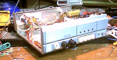
converters, switching mode power supply, power electronics, Pspice AND FINALLY, SOME PORN SHOTS: Be absolutely Icebox. |
    |
|