STABLE
HIGH-LINEARITY SAW-TOOTH GENERATOR  |
In
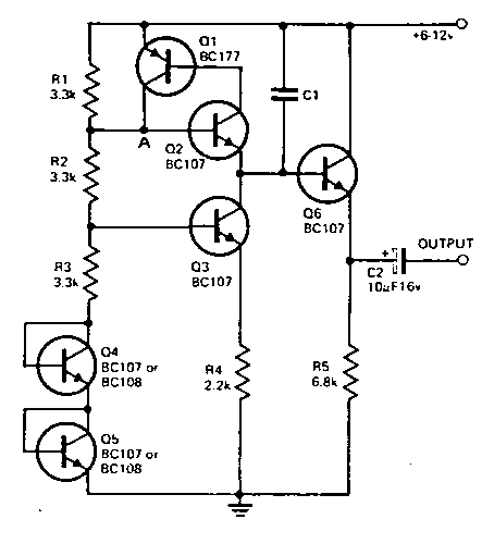
this circuit two transistors 01 and Q2 are connected so that they operate
as a unijunction transistor. Capacitor C1 is charged by a constant current
source made up of transistors 03. Q4 and Q5. This ensures a linear voltage
rise. As soon as this voltage rises to the value as found at a point A of
the Circuit (less the base emitter voltage of 02). the transistors 01 and
02 become conducting and C1 is discharged very rapidly. The voltage rise
across C1 is very linear and is applied to an emitter follower stage. This
ensures that there is no shunting effect by the load Circuit which could
be detrimental to the linearity of the output waveform. The potential divider
chain (R1-R2-R3) Contains two transistors strapped as diodes and ensures
good stability of the oscillator for variations in both supply voltage and
temperature. Frequency of operation can be calculated from the formula:
f = 1/R4.
C1
where C and R are expressed
in ohms and farads and f in Hz. |

