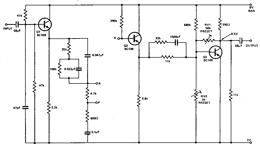
The
circuit in Fig. 1. is used to either boost or cut frequencies. When making
a recording, point X is wired to point R so that treble signals are boosted
by 10dB, and then during playback, point X is wired to point P so that the
signal from the tape, including the hiss, has the treble cut by an equivalent
amount.
|
The circuit values
are such that the overall frequency response, from record through playback,
is fiat over the range 2OHz—2OkHz. Thus the output signal after playback
is identical with the input signal before recording, but the hiss is cut
by 10dB.
RV1 sets the gain of the circuit to be unity at
low frequencies (<500Hz); RV2 is adjusted so that the collector voltage
of 03 is half the positive rail voltage. When this is set, the circuit will
function without apparent distortion with an input voltage ot upto 1.5V
r.m.s.
|
If
monitoring during record is not required, the same circuit may be used for
record and playback, with X switched between P and R as necessary.
If
monitoring during record is required, two circuits are needed, one with
X wired to A and the other with X wired to P.
For
stereo, two circuits are required. |