| VARIOUS
AUDIO CIRCUITS |

|
When
power output, harmonic distortion, frequency response are not the
absolute parameters for an amplifier, such as in the case of small
personal portable radios, operation of an amplifier in class ‘A’
does have a number of advantages.
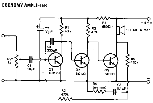
The circuit shown uses -only three transistors,
does not require an output transformer, and gives an output of between
100 — 200 mW for a battery supply of only 4.5V.
RV1 provides volume control and couples into
the amplifier through C1. The following three stages are directly
coupled.
Q1 base bias is established by resistors R2
and R5. R1 —Q1 acts as a bias potential divider for Q2 base
and similarly R3 — Q2 bias base of Q3.
R2 and R5 also form part of an overall negative
feedback loop
improving frequency response and reducing distortion.
A compromise between gain and quality results
in a choice of values for R6 and C3. C3 is a decoupling capacitor
and R6 is adjusted by trial and error. (Minimum value should be 22k.) |
| |

|
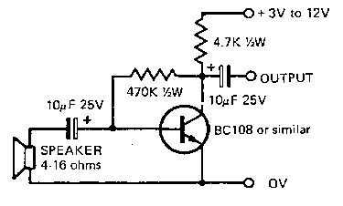
A
small loudspeaker may be used as a very effective microphone for intercoms
etc. if it is coupled via the circuit shown above.
Output is sufficient to drive practically any transistor or valve
-audio amplifier. |
| VOLTAGE
CONTROLLED AMPLIFIER |
|

|
|
| |
When
the voltage at the gate of a n-channel MOSFET is varied from 0V —
supply volts its resistance varies from about 1 kohm to several tens
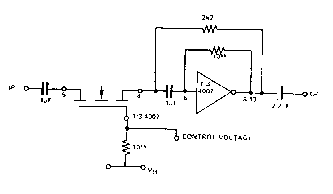
of megohms. This fact is utilised in the following VCA.
The inverter is biased into linear operation
by the 10m-ohm resistor. When feedback is
applied
thegain is set by |
_RF_
RIN |
|
By
allowing a MOSFET to be RIN and RF fixed, with the values shown as
the control voltage varies from VDD — VSS the gain of the amplifier
varies from cutoff to just over unity. |
|


